SS1-TECHNICAL DRAWING
Date:06/08/2020
Topic: Inscribed circle
To inscribe a circle in any regular polygon, rhombus or deltoid.
Procedure
- Bisect any two angles, to determine the centre of the figure, O
- Draw a perpendicular to one side from the Centre O(OA).
- With Centre O and radius OA. Draw the required circle
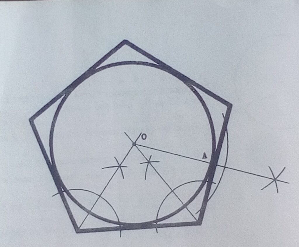
To Inscribe a Circle in any sector
- Bisect the angle (line AB).
- Draw a tangent to meet the arms extended at C and D
- Bisect one of the angles to determine the centre of the required circle O
- With centre O and radius OB. Draw the required centre
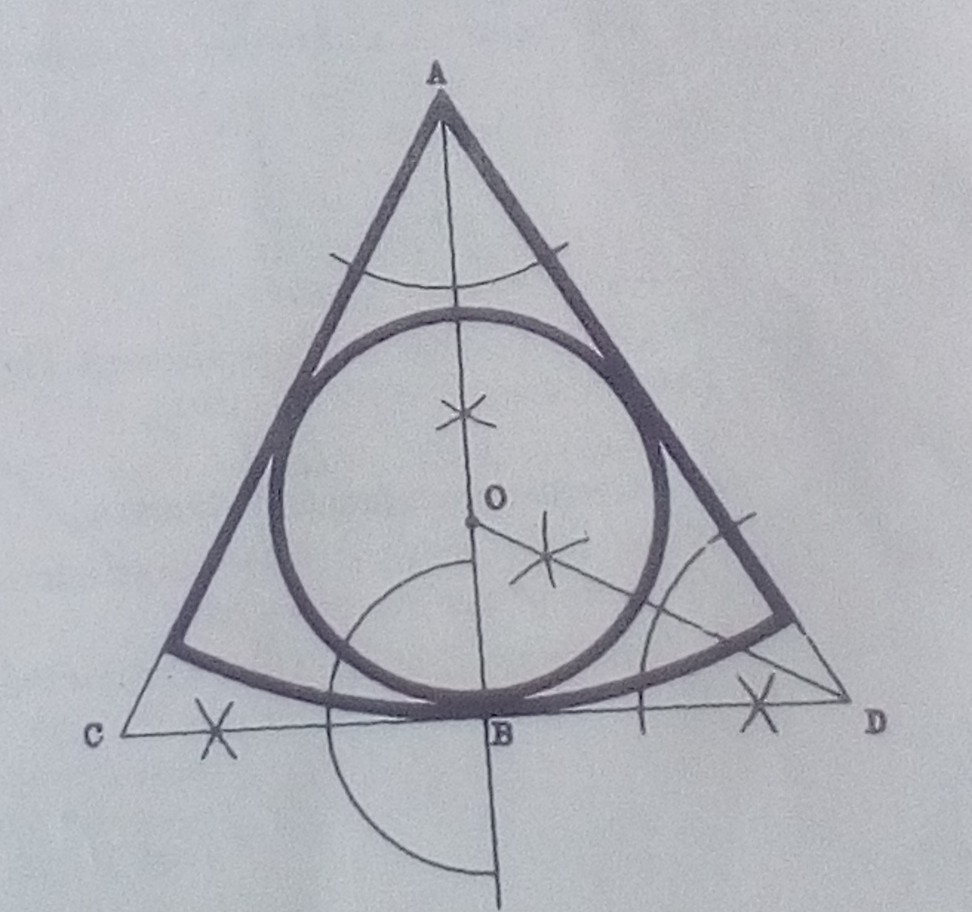
Assignment
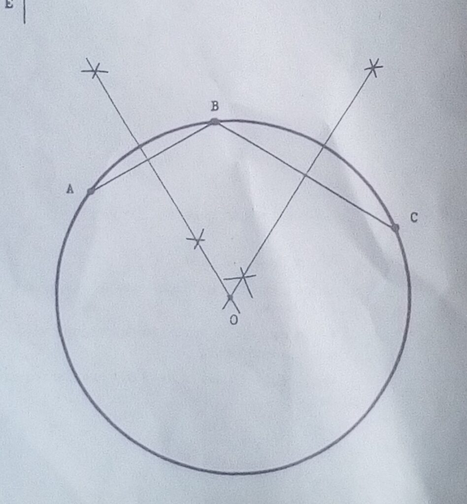
Consider page 44 of JN Green and draw a circle to pass through three given points in the following diagram.
Using the form or email below: akinsamgambol@gmail.com
Write your name, class, subject, topic and email
SS1-Technical Drawing
Date: 02/07/2020
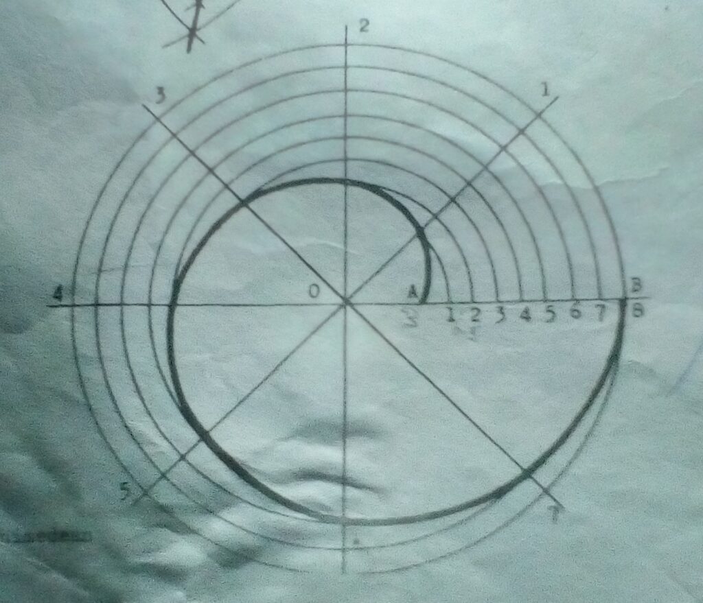
Topic: Loci-Construction of Archimedean Spiral
An Archimedean spiral is the path of a point moving uniformly along a straight line rotating about a fixed point at an even speed.
Procedure:
- Mark the pole O. Draw AO and OB equal to the given radii.
- With centre O and radius OB, draw a circle and divide it into 8 equal sectors.
- Divide AB into the same number of equal parts as there are sectors.
- With centre O and radius O1, draw an to cut radial 1. Repeat for 2,3,4,5,6,7,8. Draw a curve through the points.
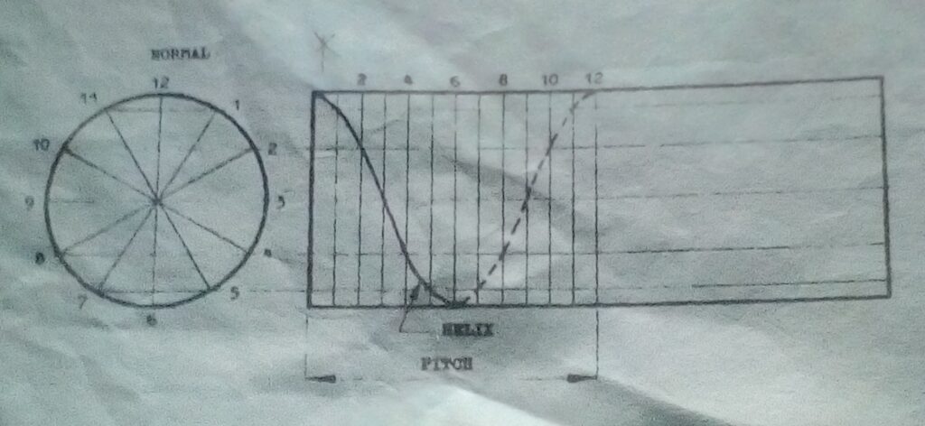
Construction of a Helix
A Helix is the part of a point moving round a cylinder and at the same time axially with the ratio of the two movements constant.
Procedure:
- Draw the front elevation of the cylinder and Project horizontal lines from 1,2,3,….on the end elevation.
- Divide the pitch into 12 equal parts. These lines intersect their corresponding horizontal lines, this mark the curve points.
Assignment
Construct the involute of a circle of radius 20mm. Hint: see page 138 of J .N Green.
Using the form or email below:
akinsamgambol@gmail.com
Write your name, subject, class, topic and email.
SS1- Technical Drawing
Date: 27/08/2020
Topic: Polygons
A polygon is a plane figure having more than 4 sides.
Kinds of Polygon
A regular Polygon has all its sides and angles equal.
An irregular Polygon has all its sides and angles unequal.
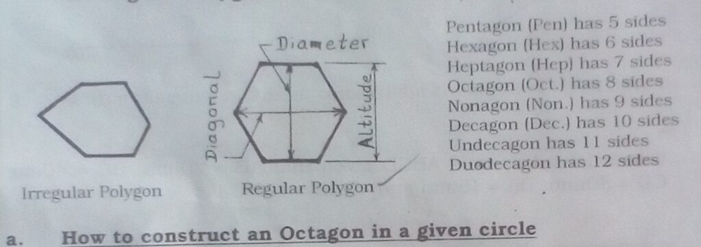
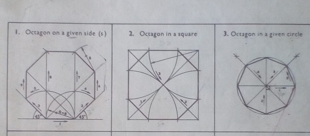
How to construct an Octagon using different methods.
Considering the previous knowledge and arrows in the Drawing numbering 1,2,3,4 etc as constructed below:
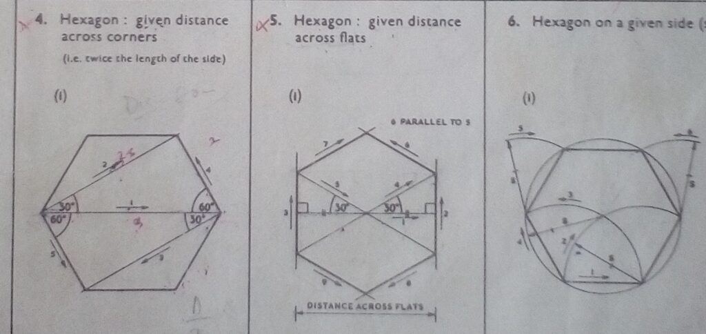
- How to a Hexagon using different methods.
Also use the direction of arrows given in the construction below:
Assignment
1.Using a general method, Construct a Nonagon given length of one side as 40mm.
- Construct a Hexagon given a diameter 80mm.
Using the form or email below:
akinsamgambol@gmail.com
Write your name ,subject class, topic and email.
SS 1- Technical Drawing
SS 1 – Technical Drawing
Date : 18/06/2020
Topic : Loci- Parabola
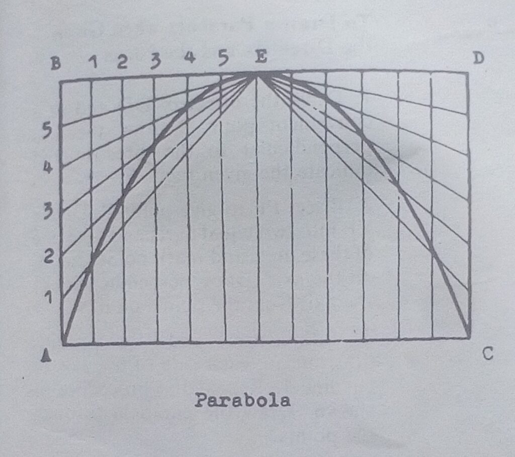
Parabola is the locus of a point Which moves so that it’s distance from the focus equals it’s perpendicular distance from the directrix.
It is the intersection of a right circular cone with a plane parallel to the element of the cone.
To Construct a Parabola,Given the Span and Height
Procedure:
- Divide AB, DC, half -span BE and half- span ED into 6 equal parts.
- With centre E radiate line to 1,2,……
- Draw vertical lines from the points on BD to intersect their corresponding radial lines to mark the curve points.
Hyperbola
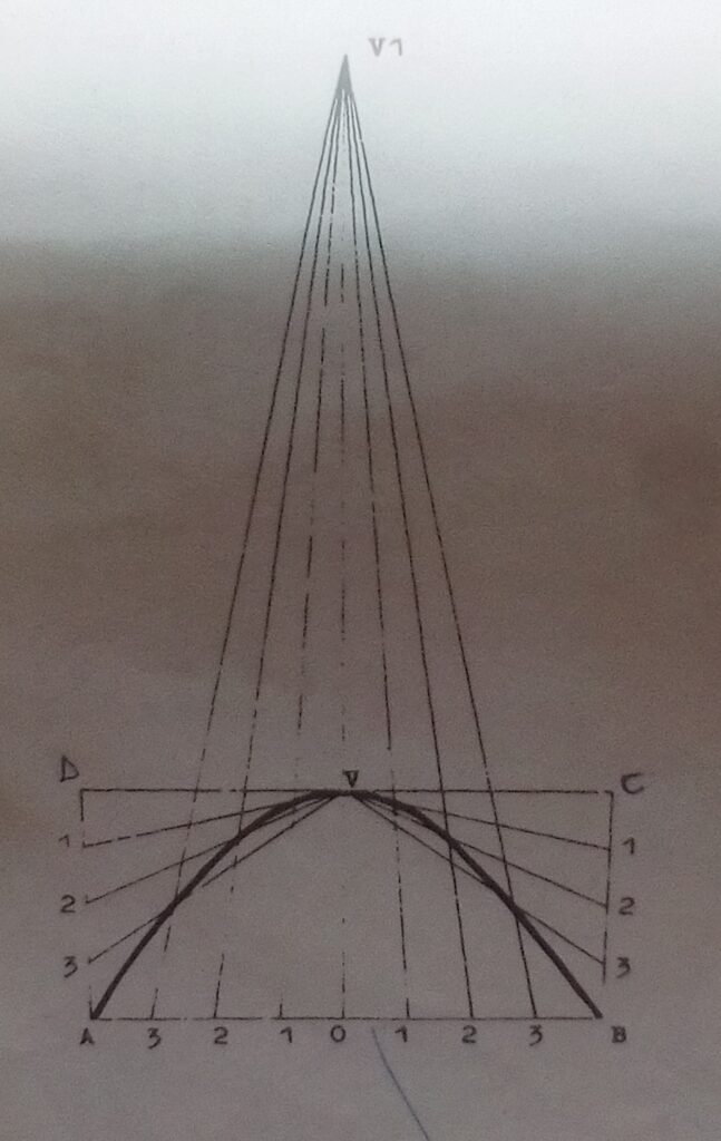
Hyperbola is a plane circle or locus generated by a point so many that the difference of the distance from two fixed points is a constant. It is also a curve formed by the intersection of a double right circular cone with a plane cutting both halves of the cone.
How to construct a hyperbola when the span, the height and the Directrix
Procedure:
- Draw the rectangle ABCD with the given Span and height.
- Bisect span AB to give point O and V.
- Extend OV and mark off VV1 equals the distance of the directrix.
- Divide AD, BC, AO and OB into any numbers of equal parts.
- Radiate lines from V and V1 to 1, 2, 3 to intersect as shown.
- Join the points with a curve to give the required hyperbola.
Assignment
Construct a parabola to find the focus and the Directrix.
Go to JN Green, page 141 for more details.
Using the form or email below:
akinsamgambol@gmail.com
Write your name, subject, class,Topic and email.
SS1 – Drawing Technical
Date : 13/08/2020
Topic : L oci
A locus i tos a path traced by a point moving in accordance with a stated rule or law of motion. It is practically applicable for the construction of machines and building shapes e.g Arcs and curves. The plural of locus is loci. Examples are Ellipse, parabola, hyperbola, helix, Archimedean spiral, involute of a circle and cycloid.
Construction of Ellipse
An Ellipse is a locus of a point moving under fixed condition to form a plane figure bounded by a curved line called circumference. The longer diameter is called major axis and the shorter diameter is called minor axis. The two axes bisect at right angle.
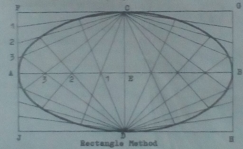
To construct an Ellipse by the Rectangle
Procedure:
- Draw a rectangle equal to the major and minor axes.Draw the axes AB and CD.
- Divide EA and AF into 4 equal units.
- Radiate lines from C through 1,2 and 3 on AF.
- Radiate lines from D through 1,2 and 3 on AE to intersect lines 1,2 and 3. These are the curve points as follows:
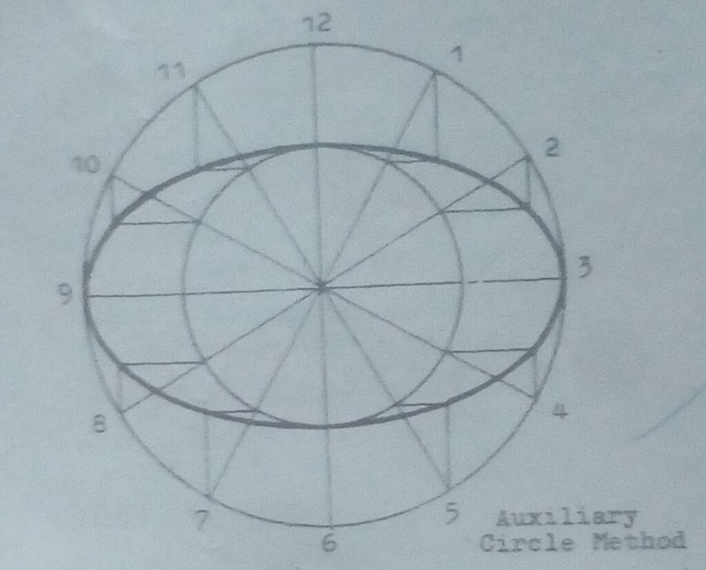
To draw an Ellipse by Auxiliary circle
Procedure:
- Draw two concentric circles equal in diameter to the major and minor axes.
- Divide the cicumference of the larger circle into 12 equal parts. Join these points to the center of the circle.
- Draw verticals from points 1-12 and draw horizontals from the points where the radiating lines cut the inner circle to intersect the verticals. These are the curve points as follows:
Assignment
Applying the principle of rectangle method above, construct an Ellipse by a Parallelogram method w ith major and minor axes 120mm, 80mm respectively.
Using the form or email below:
akinsamgambol@gmail.com.
Write your name, subject, Topic, class and email.
Date: 04/06/2020
Topic: Free Hand Drawing or Sketches.
Free hand drawing or Sketch is involves the use of free hand pencil without measurements to combine views. This is called Assembly drawing.
Here, we are to use the principle of isometric projection to establish our axes at 30 degrees without using protractor or set squares.
Let’s consider the following views drawn in 1st angle projection. Make a free hand isometric drawing.

SOLUTION
Let’s first establish our vertical, 2 receding lines as follows:


Assignment
Make a free hand isometric drawing of the following views drawn in 1st orthographic projection.
Using the form or email below and the upload link t the top of this page.
Write your name ,subject ,class ,Topic and email

SS1-TECHNICAL DRAWING
Date: 28/05/2020
Topic: Equal Areas of Plane Figures
A plane is flat smooth surface while plane figure is an object that is drawn on a flat smooth surface. Therefore, plane Figures like square, rectangle, parallelogram, polygon, triangle, rhombus e.t.c can be constructed on the same plane having the same areas.
- To construct a Square Equal in Area to a given Rectangle.
Procedure:
I.Draw the given rectangle ABCD
II.Extend AB at B.With centre B and radius BC draw an arc to touch AB extended at E.
III.Erect a semicircle on AE. Extend BC to touch it at F. BF is the length of the square.

Assignment
Construct a Square Equal in Area to a given Parallelogram ABCD with AD = 80mm, < ADC = 75degrees and CD = 50mm.
Answer the above question using the form or e – mail below:
akinsamgambol@gmail.com.
Write your Name, Class, Subject, Top
SS1 – Technical Drawing
Date: 20/08/2020
Topic:
ORTHOGRAPHIC PROJECTION
This is a method of drawing of an object in three dimensional form with sufficient clarity and details. It represents the real true shape of various parts and hidden details of the object to be fabricated. All details which are not possible in lsometric projection are now shown in orthographic projection.
Views of orthographic projection .
- Front Elevation (main view).
- Plan ( Top view)
- End Elevation (side view)
PRINCIPAL PLANE 1.Vertical Plane-Front and end elevation are drawn on this plane. 2. Horizontal plane- Only the plan is drawn on this plane.
Angle of Projection
*First Angle Projection: The Front Elevation is up, the Plan is down While the end Elevation is placed across the end of the front Elevation.
2. Third Angle Projection: The plan is up, the front Elevation is down While the end Elevation is placed across the end of the front elevation.
Note: In first Angle Projection, the left end elevation is drawn on the right side of the front elevation and vice versa while in third Angle Projection, the left end elevation is drawn on the same left side of the front elevation and vice versa.
Assignment
Consider this block and Draw in first Angle Projection using the form (s) below:
1, the front elevation in the direction of arrow K.
2, the plan.
3, the right end elevation.
