SS3-Technical Drawing
Date:06/08/2020
Topic: Development of Figures/ Past WAEC Examination review
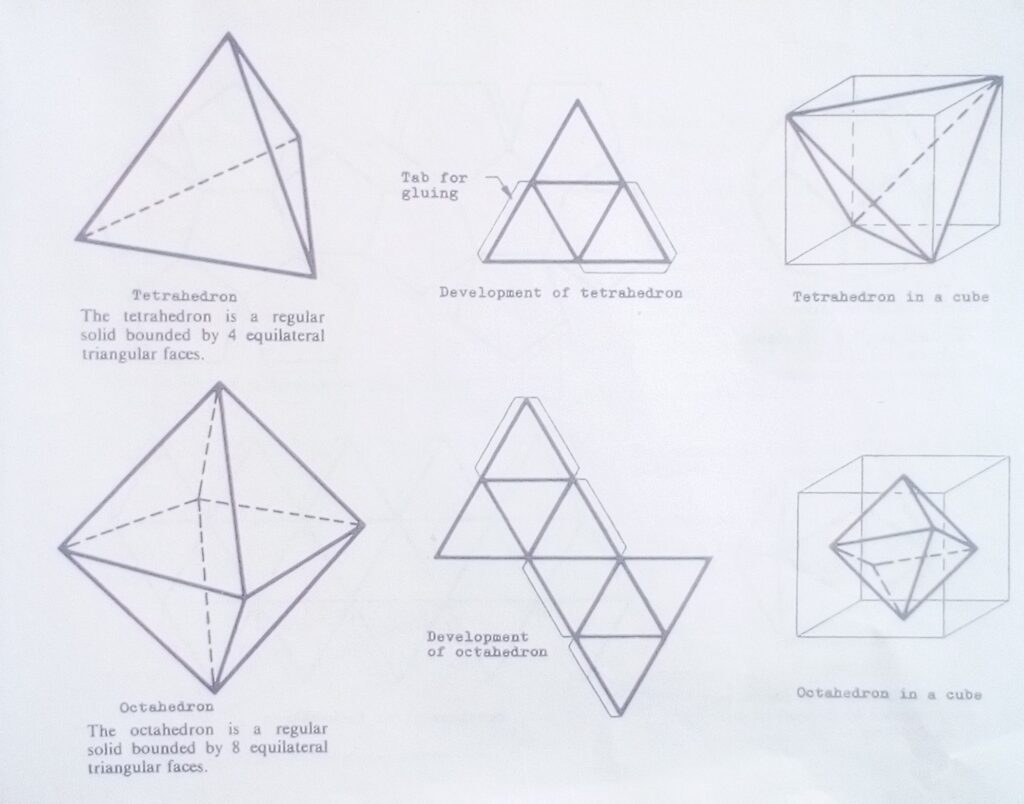
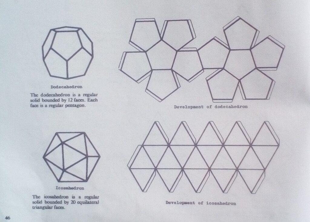
Development is the method of unfolding of objects drawn in Isometric or Oblique form. Study the following blocks and their corresponding development:
Assignment
Make a free hand drawing of the following instruments:
- Spirit level
- Single open ended spanner
- Pincer
- Star and flat screen driver
- F clamp
- G clamp
- Ball pein Hammer
- Block Head Hammer
- Spade
- Shovel
- Mitre square
- Steel rule
- Centre punch
- Allen key
- Washer
- Stud
- Wing nut
- Thumb screw
- Grub screw
- Split pin
- Taper pin
- Spring washer
Using the form or email below: akinsamgambol@gmail.com
Write your name, subject, class, topic and email
SS3-Technical Drawing
Date:02/07/2020
Topic: Auxiliary views (3)
Considering our previous discussion and construction of how to draw an auxiliary plan i.e, the projection lines are coming from the front elevation.
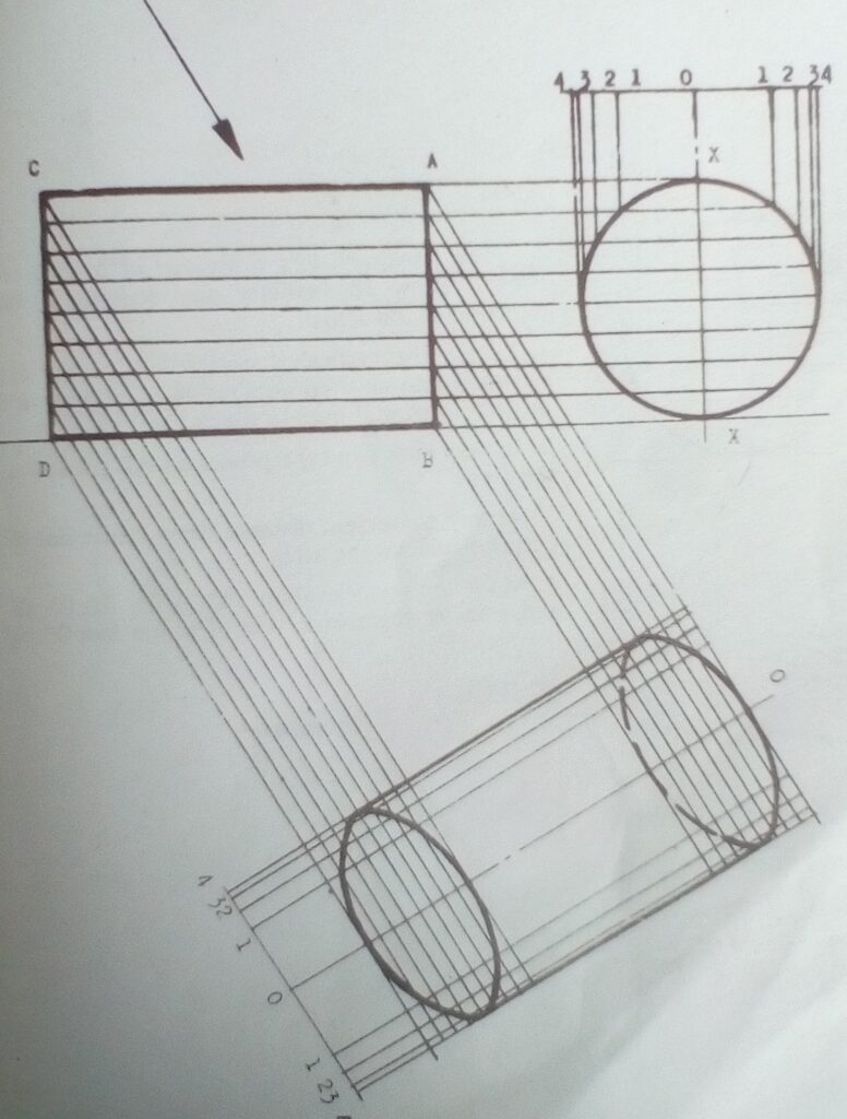
Let’s consider the front and end elevations of a cylinder as shown below:
Procedure:
1.Divide the vertical diameter XX of the end elevation into an even number of equal parts and Project horizontal lines to the front elevation ends AB and CD. Continue your projection lines & construction as follows:
Assignment
Go-to page 122 of J.N Green
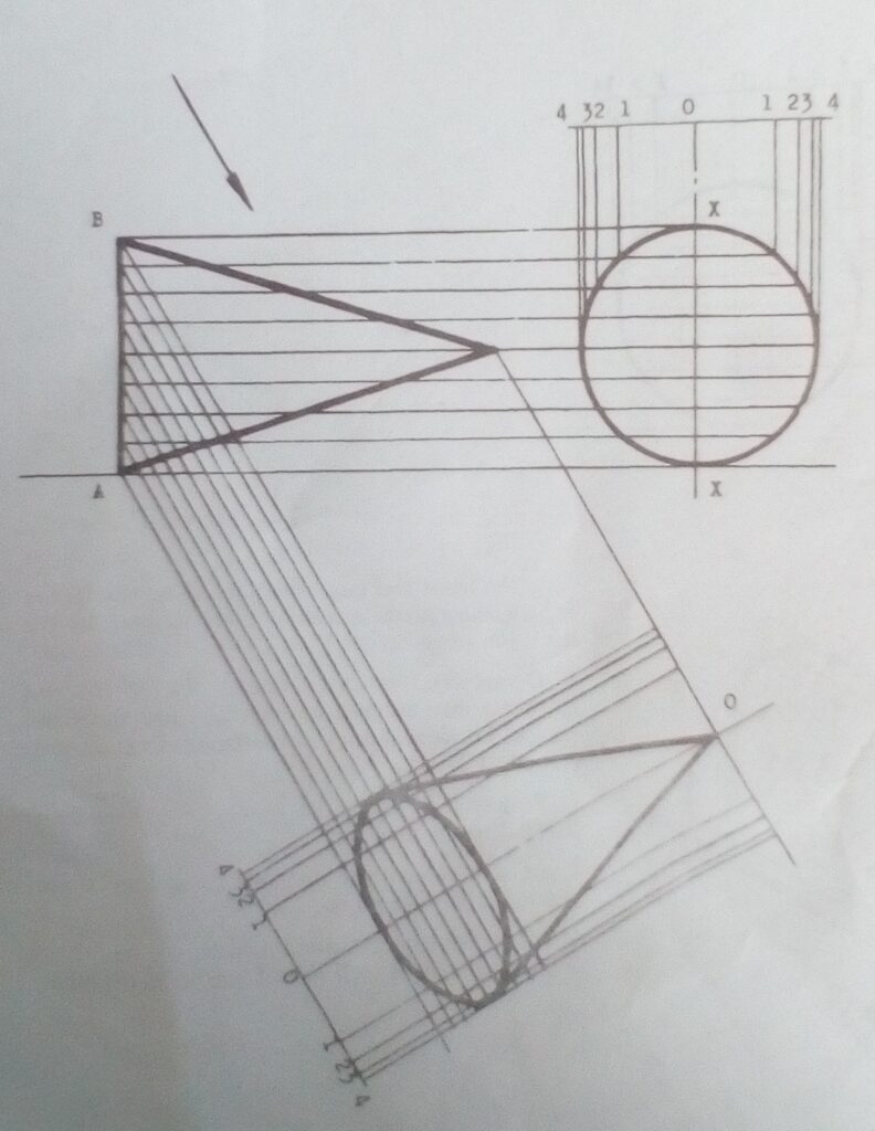
Construct the front and end elevations of a cone are shown below. Draw an auxiliary plan looking in the direction of the arrow. Follow the procedure and draw:. Using the form or email below:
akinsamgambol@gmail.com
Write your name, subject, class, topic and email.
SS3 – Technical Drawing
Date : 25/06/2020
Topic : Mechanical Assembly Drawing(WEAC REVIEW)
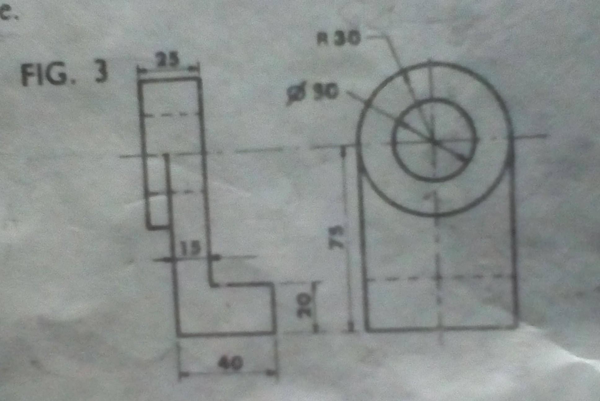
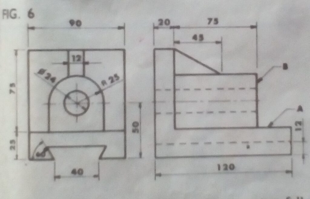
Mechanical Assembly Drawing is a method of putting the Orthographic views of engine parts together to produce Isometric block.
It could be by drawing or sketching views.
To draw the Assembly of views involves measurements while To sketch the same Assembly of views involves the use of free hand. Answer the following questions based on our previous knowledge on mechanical drawing.
1.Draw an isometric block of the components shown in the figure below.
2.Make a free hand isometric projection of the sliding bracket shown in the figure below.
Using the form or email below:
akinsamgambol@gmail.com
Write your name, subject, class, topic and email.
SS 3 – Technical Drawing
Date: 18/06/2020
Topic : REVIEW OF WEAC & GCE PAST QUESTIONS ON AUXILIARY PROJECTION.
AUXILIARY PROJECTION
When an object is viewed at an angle other than 90 degrees to its surface, the lines projected from each point on the object in that direction of view is called Auxiliary projection.
Auxiliary plan- projection lines are coming from the front elevation at 45 or 60 degrees.
Auxiliary elevation- projection lines are coming from the plan at angle 45 or 60 degrees.
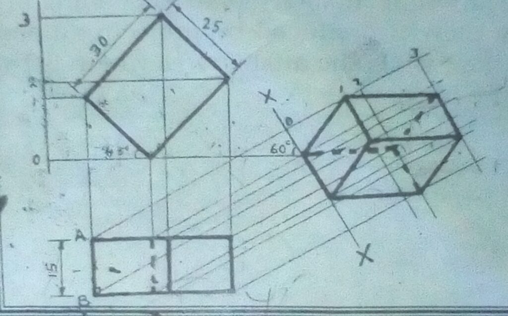
Assignment
- Complete the auxiliary plan of the prism shown below.
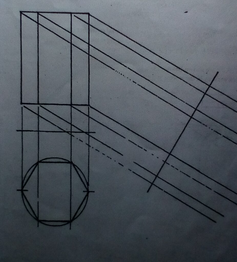
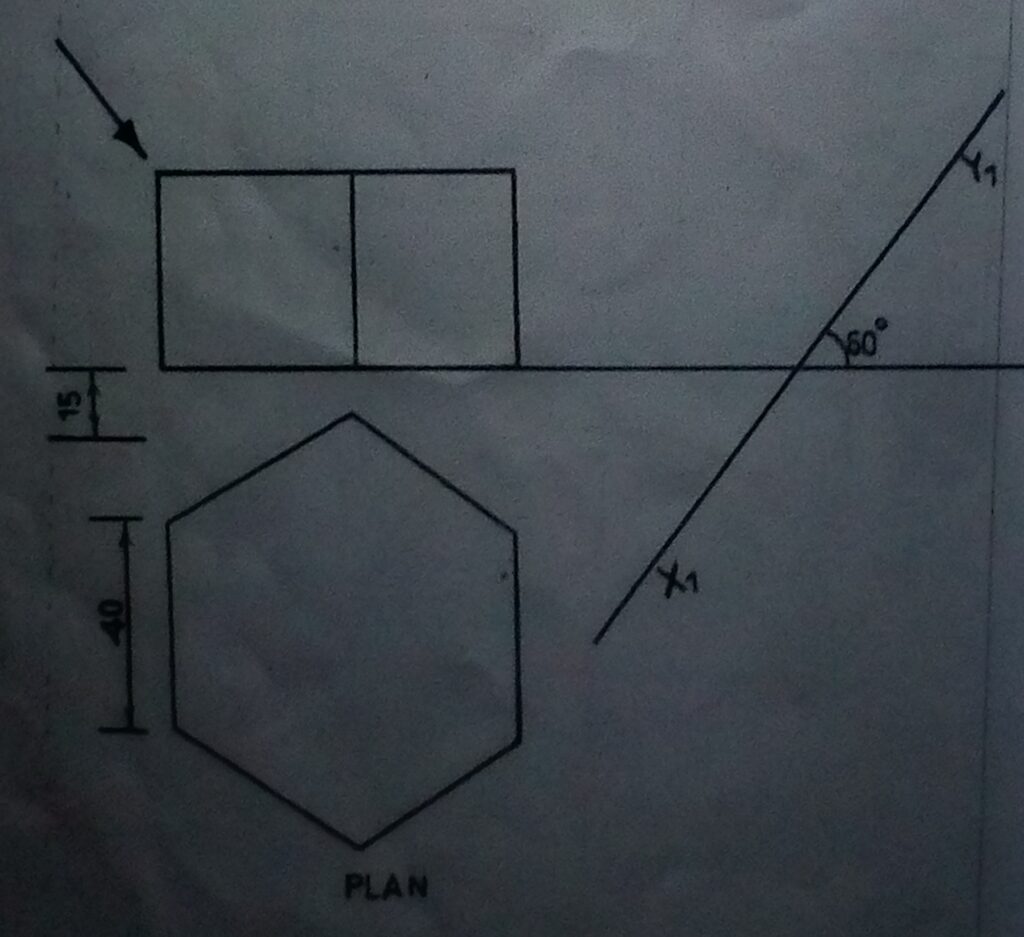
- The front elevation and the plan is regular Hexagonal prism are shown below. Draw the auxiliary plan on plane X1Y1. Show all hidden details.
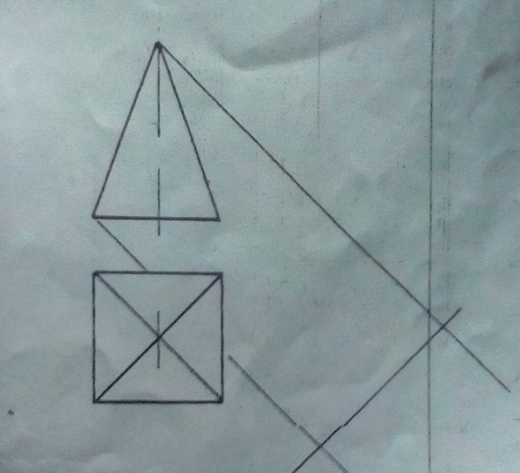
3.Complete the construction of the auxiliary plan of a square based pyramid started in the figure below.
Using the form or email below:
akinsamgambol@gmail.com
Write your name ,subject, class, topic and email
|
Upload files
|
|
|
|
|
|
|
SS 3- Technical Drawing
Date:13/08/2020
Topic: Sections
Section means cutting or slicing off part of an object or building to show clearly the inside so as to give sufficient information that will enable easy manufacturing. When an object is cut and it’s upper part removed it is called a truncated object.
The remaining part of a truncated object is called a frustum. Thick long chains with arrow head are used to show the line of cutting (cutting plane) and direction of view. The part behind the cutting plane must be removed. Do not show hidden details on sectional views. The sectional surface must be hatched using thin short lines, at 45 degrees to the horizontal.
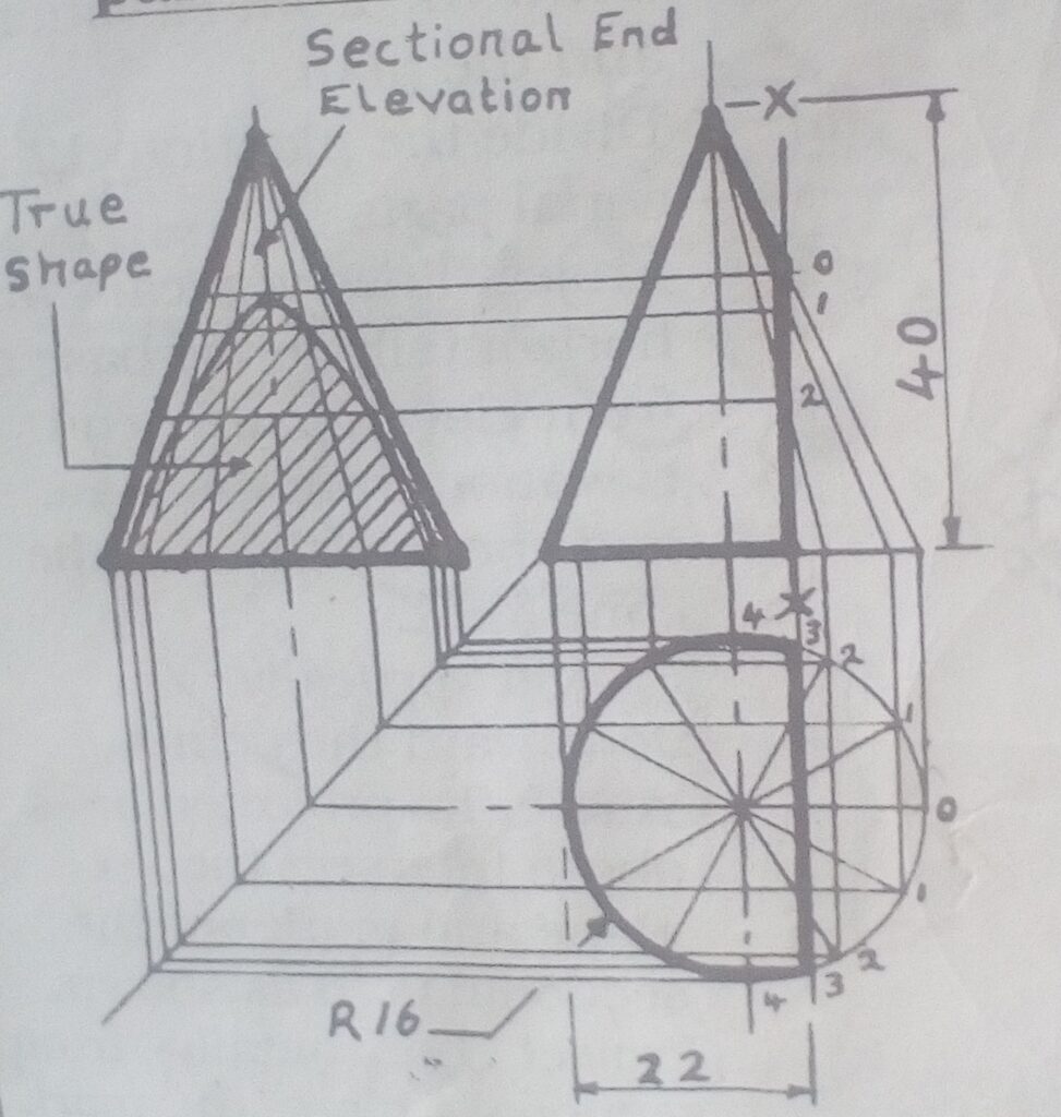
How to construct the sectional plan, sectional end Elevation and true shape of a cone sectioned vertically parallel to its Axis.
Procedure:
- Draw the front elevation with cutting plane.
- Produce the sectional plan and divide the circumference into 12 equal parts.
- Project lines from point 0,1,2,3 and 4 on the plan to the base of the front and end elevation and connect it to their apex.
- From points 0,1,2,3 and 4 on plan, Project lines horizontally to intersect corresponding lines on the end elevation.
- Trace the points of the intersection to give the required True shape( Hyperbola)
Assignment
Go-to page 88 of the old Basic construction method text book for details.
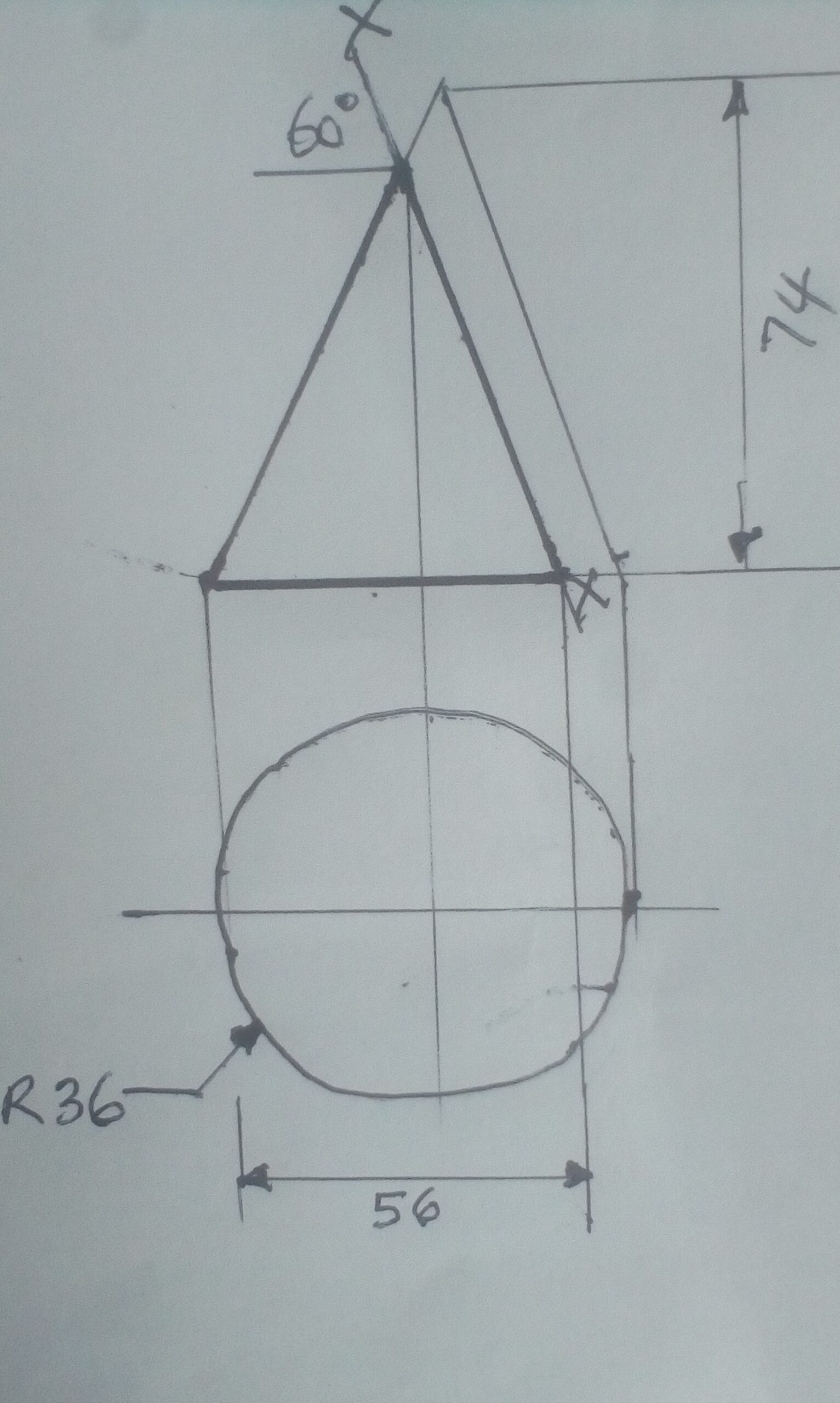
Construct the sectional plan, sectional end elevation and true shape of a section of a cone with cutting plane XX parallel to one of the sides as follows:
Using the form or email below:
akinsamgambol@gmail.com
Write your name, subject, class, topics and email.
Date: 04/06/2020
Topic: DrawingSections in Mechanical engineering Drawing.
SECTIONS
Hidden details are shown by lines of short dashes but a clearer way of showing hidden details is by drawing sections. The object is imagined to be cut through by a flat sheet of perspex called the cutting plane A cutting plane is indicated by a heavy center line and arrow as shown and the part behind the plane is removed. We now look at the object in the direction of the arrows draw the view( section). The actual material cut by the plane is with lines at 45 degrees. Hidden detail is not usually shown on sectional views.
Consider the following orthographic views drawn in first angle projection.
We are going to drawthe:
i.given viewsii.draw sections AA, BB and CC as follows:

Assignment.
The drawing below shows part of engine. Bolt the bracket on the outside of the casting and draw in third angle projection:
I.A section on plane XX.
ii.A plan
III.An end elevation looking in the direction of arrow A.
Note: Go-to J.N Green page 207, No 86.for details.
Using the form or email below and the upload link at the top of this page.
Write your name, subject, class, topic and email.

SS3-TECHNICAL DRAWING
Date:28/05/2020
Topic: Mechanical engineering Drawing
Two views of engine parts are shown in first angle projections below :
To Draw section on plane XXis shown as follows:

Hellow students. How are you doing? Hope this lockdown has not disoriented you. You are welcome to this platform. Now, let’s get down business.
Assignment
Considering the above drawing and sectional example. Draw:
- The given views
- Right end elevation
Using the form or email below.
Write your name, subject, class, Topic & email.
REVIEW OF 2nd TERM WORK
MECHANICAL DRAWING
This is a drawing done by using special instruments that allow you to draw machines, buildings etc in a very precise and accurate way. It can be drawn either in first or third Angle orthographic projection.
Cutting planes can pass through each elevation so as to determine details information about the machine from which sections can be drawn on plane. Consider this example:
ASSIGNMENT
Considering the interpretation of cutting plane on views of orthographic drawing and study the views carefully.
Draw in First Angle Projection using the form (s) below:
- section on Plane AA.
- PLan
- Left end Elevation.

